
Your ignition curve depends on an accurate reference. Before tuning an MSD 42351 or programming a Zeeltronic MS01, establish exactly where each pickup detects the flywheel magnet relative to its piston’s top dead center.
This guide covers Yamaha two-stroke twin-cylinder setups with aftermarket total-loss ignition and marked flywheels. It follows the JetSkiNerd workshop method, with separate instructions for the MSD LED and Zeeltronic software monitor.
Understand the reference first
Top dead center (TDC)
The piston’s highest position in its cylinder: your zero-degree reference.
Before top dead center (BTDC)
Crankshaft position before the piston reaches TDC, measured in degrees. A pickup event at 35° BTDC happens earlier than one at 32° BTDC.
Static timing or static angle
In this guide, the mechanical angle before TDC where the pickup detects the approaching magnet. The ignition uses that event as its spark-timing reference.
Maximum running advance
The greatest spark advance intended in the running program. A 35° pickup reference does not mean you should run 35° of spark advance.
Viewed from in front of the jet ski, looking at the flywheel, the Yamaha engines covered here turn clockwise. Make every final measurement clockwise, as the magnet approaches the pickup. Do not use the event as the magnet leaves it.
Small flywheel or pickup movements can represent several crankshaft degrees. Excessive advance can damage an engine. Select the running curve for the specific engine, compression, fuel and application.
Tools and preparation
- A spark-plug-hole dial indicator with the correct adapter and sufficient probe travel.
- A marked flywheel, fine-tip marker and stiff wire for a fixed pointer.
- Hand tools, suitable mounting hardware and specified threadlocker.
- For the MS01, the correct ZeelProg software and programming cable.
Consider the Motion Pro 08-0250 timing kit or Starting Line Products 20-92. Both include a dial indicator and 14 mm spark-plug-hole adapter. Check plug-hole angle, thread fit, reach and clearance against your cylinder head.
Amazon searches: Motion Pro 08-0250 and SLP 20-92. These are search links; availability and sellers vary.
No timing marks? Use a degree wheel and fixed pointer to establish TDC and create accurate angle marks before following this guide. A piston stop and degree wheel are another TDC method; never use the starter against a piston stop.
Switch ignition power off for gauge installation and mechanical adjustments. Turn the engine by hand. When powering the ignition, follow its grounding instructions for removed plugs, avoid touching high-voltage parts and keep sparks away from fuel vapors.
Find TDC and install a pointer
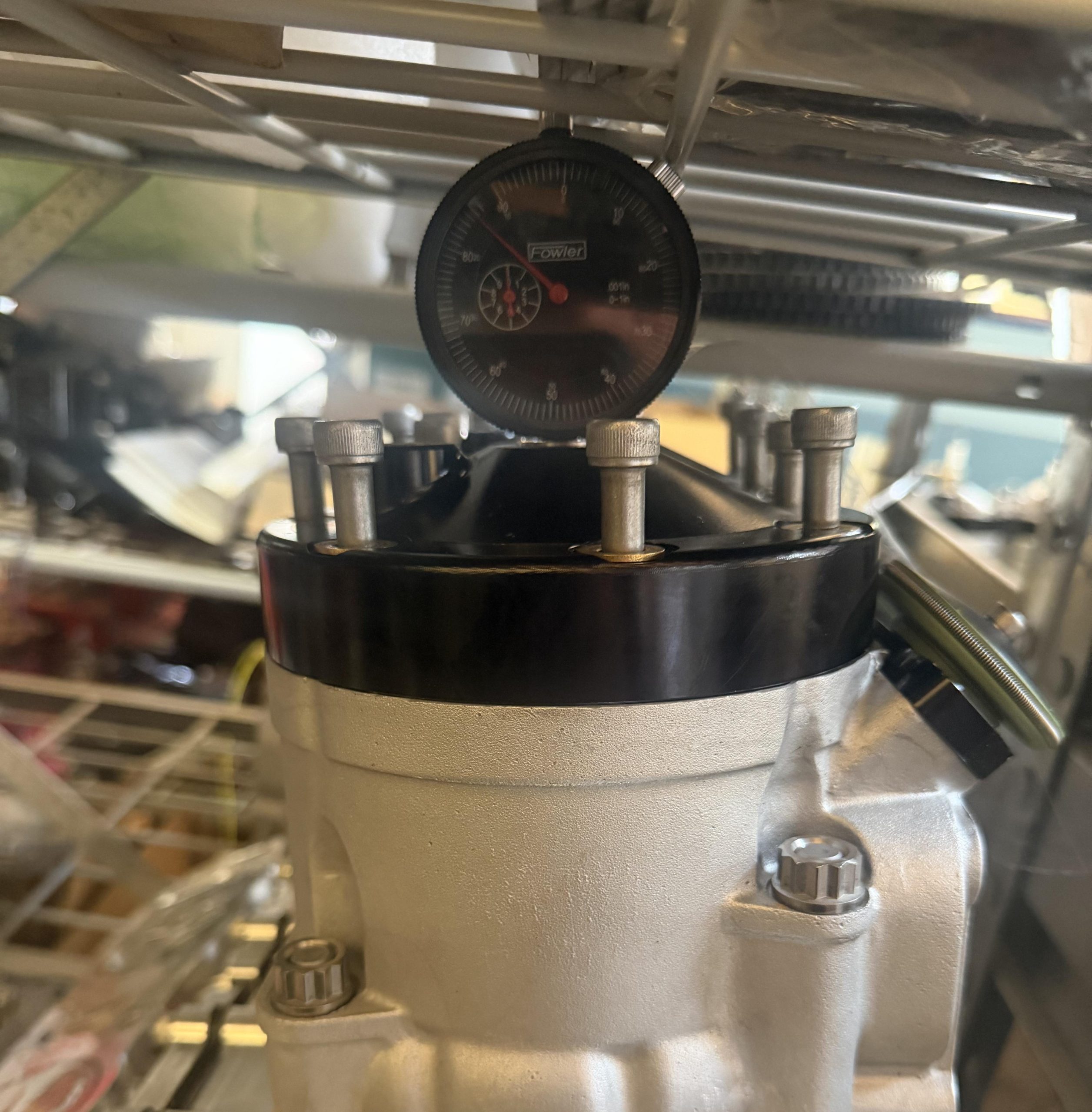
- Install the indicator in cylinder 1: the front cylinder nearest the flywheel on these Yamaha twins. Ensure correct piston contact and enough probe travel to avoid bottoming out.
- Find the peak. Rotate the flywheel slowly. Near the maximum reading, use very small movements in both directions to locate the highest piston position.
Photo placeholder: dial indicator installed in the cylinder. Add a photo showing the spark-plug-hole adapter and indicator placement while finding top dead center. - Account for piston dwell. The piston moves very little near TDC, so a seemingly stationary needle can cover several crankshaft degrees. For a precise cross-check, use a degree wheel to record crank angles at the same small piston drop on either side of TDC. Bisect the angular interval containing TDC. Do not simply choose one edge of the apparent plateau.
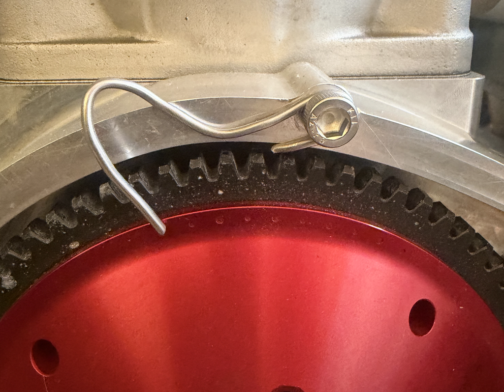
- Make a fixed pointer. Form stiff welding wire and secure it to a suitable flywheel-cover mounting point. Position the tip close to the scale without touching the flywheel. Solder can work if it remains rigidly in position.
- Set zero. At true TDC, align the pointer with 0°. For unlabeled dots, first identify the manufacturer’s TDC dot. On the MSD dot pattern discussed here, it is the leftmost dot in the timing group; other flywheels may differ.
Photo placeholder: pointer aligned with the flywheel’s zero-degree mark. Add a close-up showing the fixed pointer and confirmed TDC mark. - Repeat the check. Move away and find TDC again. The same zero alignment should return. Look squarely at the pointer to avoid parallax.
Choose and mark the static angle
At JetSkiNerd, we commonly use a 35–36° BTDC mechanical reference for the setups discussed here. Confirm that it suits your ignition and intended curve.
For an MSD flywheel with dots every 5°, count seven intervals from zero: 5°, 10°, 15°, 20°, 25°, 30°, 35°. Highlight the 35° dot with a marker. Do not count zero as the first 5° interval. A 36° target requires measuring the additional degree; 5° dots alone cannot locate it precisely.
MSD 42351: use the setup LED
- Select setup mode. With power off, set bank 3, selector S4 ON for LED operation. Cycle ignition power after DIP-switch changes. Keep removed plugs connected and grounded as the manual instructs.
- Back up. Rotate counterclockwise beyond the target, far enough to put the magnet before its approaching-pickup event.
- Approach clockwise. Turn very slowly until the LED first illuminates. Find the first repeatable transition. If you overshoot, back up before the event and approach clockwise again.
- Read the angle. Record the BTDC reading at the pointer. Compare the number with your target instead of relying on a left/right description.
- Adjust. Switch power off. On this clockwise-rotating arrangement, move the pickup plate clockwise to retard the event, counterclockwise to advance it. Make small changes, secure the plate and repeat.
| Measured event | Meaning | Pickup adjustment |
|---|---|---|
| 38° BTDC | 3° too advanced | Slightly clockwise |
| 32° BTDC | 3° too retarded | Slightly counterclockwise |
| 35° BTDC repeatedly | At target | Secure and recheck |
The setup selector and LED procedure appear in the multi-channel manual linked from our 42351 guide, pages 4–5. Match its switch labels to your unit.
Zeeltronic MS01: use the software monitor
Connect the PDCIS-MS01, read and save its configuration, select the installed pickup type and open Monitor. The manual describes a Pickup trig status that reads “ok” when the connected pickup detects the nearby magnet.
To locate the mechanical pickup reference, back up, approach slowly clockwise and record where the relevant pickup status first changes. Repeat for consistency. Adjust mounting position as needed, enter the measured angle in Static Angle, then program the unit and confirm success.
Static Angle must exceed maximum commanded advance. See the MS01 manual for parameter definitions.
Check both cylinders independently
Setting the front pickup does not establish the rear cylinder’s timing. In our workshop, we have encountered MSD pickup arrangements with several degrees of difference between cylinders. Check Hall-sensor mounting positions independently too.
Find the rear cylinder’s own TDC. If there is no verified rear-cylinder scale, keep the pointer fixed and use a degree wheel to create a distinct rear-cylinder zero and BTDC marks. Label the two sets clearly. Do not use the front cylinder’s zero as though it were rear-cylinder TDC.
Record both static angles. Where the build calls for equal timing, adjust the individual pickups until they match. Recheck both after tightening: rotating the whole plate can change both readings.
Freestyle workshop tip: equal cylinder timing is our usual objective on these builds. Some installations require additional individual adjustment beyond the original mounting-hole travel. Carefully elongating mounting holes may be necessary. This is comm only seen on MSD pickup plates where the rear cylinder is retarded around 4 degrees from the factory. We’ve also observed considerable cylinder to cylinder discrepancies with MS01 hall sensors.
Secure the hardware and set running advance
Use red threadlocker on the retaining bolts for the pickup plate. Red threadlocker is generally high strength; LOCTITE 271, for example.
Recheck both trigger angles after final tightening. For the MSD, account for electronic maximum-timing retard: 35° static reference − 3° programmed retard = nominal 32° maximum advance, before additional active retard. This is our walkthrough example, not a universal Yamaha running-timing recommendation.
Use our MSD 42351 programming guide and timing-curve visualizer for the retard configuration. Return bank 3 S4 OFF for ignition operation and cycle power.